Difference between revisions of "M7941"
Jump to navigation
Jump to search
| Line 1: | Line 1: | ||
==DRV11 Parallel Line Unit== | ==DRV11 Parallel Line Unit== | ||
| − | The | + | The DRV11 is a general-purpose interface unit used for connecting parallel-line TTL or DTL devices to the LSI-11 bus over up to 25 feed of cable. It permits program-controlled data transfers at rates up to 44K words per second (with optimized programming) and provides LSI-11 bus interface and control logic for interrupt processing and vector generation. Data is handled by 16 diode-clamped input lines and 16 latched output lines. Device address is user-assigned and Control/Status Registers (CSR) and Data Registers are compatible with PDP-11 software routines. |
| − | |||
| − | |||
| − | |||
| − | |||
===Images=== | ===Images=== | ||
Latest revision as of 04:50, 11 August 2018
DRV11 Parallel Line Unit
The DRV11 is a general-purpose interface unit used for connecting parallel-line TTL or DTL devices to the LSI-11 bus over up to 25 feed of cable. It permits program-controlled data transfers at rates up to 44K words per second (with optimized programming) and provides LSI-11 bus interface and control logic for interrupt processing and vector generation. Data is handled by 16 diode-clamped input lines and 16 latched output lines. Device address is user-assigned and Control/Status Registers (CSR) and Data Registers are compatible with PDP-11 software routines.
Images
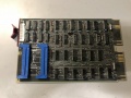
Front
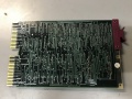
Back
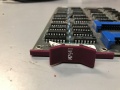
Handle


Documentation
| EK-ADV11-OP-001 | ADV11-A, KWV11-A, AAV11-A, DRV11 User's Manual |
| EK-ADV11-OP-002 | ADV11-A, KWV11-A, AAV11-A, DRV11 User's Manual |