Difference between revisions of "A8000"
(→Images) |
|||
| (5 intermediate revisions by the same user not shown) | |||
| Line 1: | Line 1: | ||
| − | ==ADV11-C Analogue-to-digital | + | ==ADV11-C Analogue-to-digital converter== |
| + | |||
| + | The ADV11-C is an LSI-11 analog input printed circuit board, a8000. It accepts up to 16 single-ended inputs, or up to 8 differential inputs, either unipolar or bipolar. A unipolar input can range from 0V to 10V. A bipolar input can range from -10V to +10V. The ADV11-C also has a programmable gain on those inputs of 1, 2, 4 or 8 times the input voltage. | ||
| + | |||
| + | Analog-to-digital (A/D) conversions are started by a program command, an external trigger, or a real-time clock input. When the program command sets the A/D START bit in the control/status register, the ADV11-C starts the A/D conversion on the input channel selected. | ||
| + | |||
| + | The ADV11-C changes the analog input into digital data. The digital data goes to the A/D data buffer register and waits for a programmed data transfer to the LSI-11 processor or memory, or the ADV11-C puts an interrupt request on the LSI-11 bus and waits for the interrupt request to be acknowledged. | ||
| + | |||
===Images=== | ===Images=== | ||
<gallery> | <gallery> | ||
| − | File: | + | File:A8000-1.jpg|Front |
| − | + | File:A8000-2.jpg|Back | |
| − | + | File:A8000-3.jpg|Handle | |
| − | File: | ||
| − | File: | ||
| − | |||
| − | |||
</gallery> | </gallery> | ||
| + | |||
| + | ===Documentation=== | ||
| + | {| class="wikitable" | ||
| + | |[[media:EK-AXV11-UG-002.pdf|EK-AXV11-UG-002]]||LSI-11 Analog System User's Guide | ||
| + | |} | ||
Latest revision as of 16:07, 9 August 2018
ADV11-C Analogue-to-digital converter
The ADV11-C is an LSI-11 analog input printed circuit board, a8000. It accepts up to 16 single-ended inputs, or up to 8 differential inputs, either unipolar or bipolar. A unipolar input can range from 0V to 10V. A bipolar input can range from -10V to +10V. The ADV11-C also has a programmable gain on those inputs of 1, 2, 4 or 8 times the input voltage.
Analog-to-digital (A/D) conversions are started by a program command, an external trigger, or a real-time clock input. When the program command sets the A/D START bit in the control/status register, the ADV11-C starts the A/D conversion on the input channel selected.
The ADV11-C changes the analog input into digital data. The digital data goes to the A/D data buffer register and waits for a programmed data transfer to the LSI-11 processor or memory, or the ADV11-C puts an interrupt request on the LSI-11 bus and waits for the interrupt request to be acknowledged.
Images
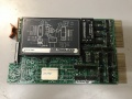
Front
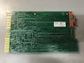
Back
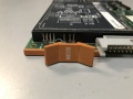
Handle


Documentation
| EK-AXV11-UG-002 | LSI-11 Analog System User's Guide |